Forum Replies Created
-
AuthorPosts
-
 UmbertoModerator
Dear Anshul,
as I have already told you the error at position 107,34,0 is that you are connecting a layer 0 via to a layer 3 Nucleation.Read my previous post and consider that it is not allowed to pass from layer one to layer 3 without placing a nucleation on layer 2.
Regards,
UmbertoUmbertoModeratorDear Anshul,
consider to always attach the qll, it is the best way to see where the problem is.
Going back to your problem, you are connecting a layer 0 via to a layer 3 Nucleation. The coordinates that you can read in the log are the one of the qcc. The layout is always “moved” to the top left corner before generating the qcc and the VHDL.Another problem in your layout, should be just warnings, are the pad unconnected. Consider vias as “T” connection to another plane. If you need just to connect the other layer and terminate the line you can use the pad. The example shows what I’m saying.
Umberto
Attachments:
UmbertoModeratorDear Anshul,
you are using the output pin in a wrong way. You have to rotate them by 180°.On the other hand, MagCAD can work with very complex circuits, up to 10000 element on more than 10 layers, so don’t worry 😉
Looking at your screenshot it seems ok.If any error is present the log file will tell you where to look in order to find it.
Best regards,
UmbertoUmbertoModeratorDear Peyman,
please attach the “.qll” of your xor gate.
Umberto
UmbertoModeratorDear Peyman,
there was a bug in the import method preventing correct simulation. The next release of MagCAD will solve the issue. Please update the tool as soon as the update is released, and generate again the component to get also a template of testbench compatible with ToPoliNano.
Umberto
UmbertoModeratorDear Chinmay,
max frequency depends on the critical path among to nucleation centers. It is automatically calculated by the tool during VHDL extraction. You can retrieve it looking clock signal during simulation.
Umberto
-
This reply was modified 6 years ago by
 Umberto.
UmbertoModeratorDear Peyman,
MagCAD vhdl files are not valuable description for ToPoliNano.
You can use that vhdl to simulate your design with standard HDL simulator (modelsim for example).
If you want to simulate your design with ToPoliNano you can import the layout directly:
-file->import layout
-select from disk the “.qll” file you want to open.
-simulate it providing a valid testbench.Please, consider that the automatic testbench generated by MagCAD is not valid for ToPoliNano. You should remove all the clock processes to use it inside ToPoliNano.
Umberto
UmbertoModeratorHi Divyang,
please do not modify the automatic generated VHDL file. The easiest way to input a fixed ‘0’ in a iNML design is to place an input pin and then use the testbench to force the value. You should give a mnemonic name to that input, such “fixed_0” and then assign the value 0 in the testbench.
The other errors should be simple syntax errors. Please have a look to the VHDL cookbook for help.
Umberto
UmbertoModeratorHi Divyang,
you are right. library_pnml.vhd is not needed, the files needed for simulation are
– <circuit_name>.vhd
– library_inml.vhd
– <circuit_name>_TB.vhdBack to your error, it seems you are writing a sort of mixed VHDL/VERILOG 🙂
Please, be careful of writing correct VHDL statement, like the one in the example of “stimuli process” in the automatically generated testbench.in1<='0'; in2<='0'; wait for 30 ns;Umberto
UmbertoModeratorHi Saurabh,
in pNML technology latency depends on your design, and on technological parameters. In the last version of MagCAD we did some changes in the default technological parameters, leading to possible different results. The value reported in the paper refers to our layout using the described parameters. Furthermore, we highlighted the maximum latency among the output in the paper: this is the critical value.Umberto
UmbertoModeratorHi,
I tried your layout and everything works fine.
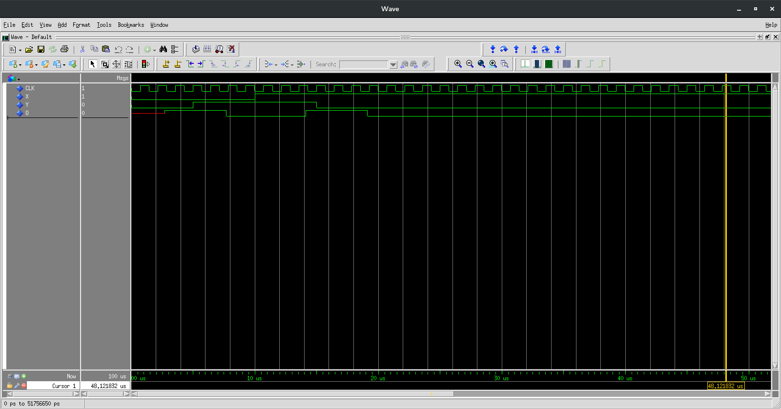
Please find below the TB, with a correct stimuli process, and attached a snapshot of the simulation.
Remember that you have to ADD YOUR STIMULI in the Testbench template.library ieee; use ieee.std_logic_1164.all; use ieee.numeric_std.all; use work.components_pnml.all; use work.definitions_pnml.all; entity tb_pNML_custom_XORNEW is end tb_pNML_custom_XORNEW; architecture Behavioural of tb_pNML_custom_XORNEW is signal CLK : std_logic; signal O :std_logic; signal O_param : param_data := (others => 0.0); signal X :std_logic; signal X_param : param_data := (others => 0.0); signal Y :std_logic; signal Y_param : param_data := (others => 0.0); component pNML_custom_XORNEW is port( O: out std_logic; O_param: out param_data := (others => 0.0); X: in std_logic; X_param: in param_data := (others => 0.0); Y: in std_logic; Y_param: in param_data := (others => 0.0); CLK: in std_logic); end component; begin DUT : pNML_custom_XORNEW port map(O => O, O_param => O_param, X => X, X_param => X_param, Y => Y, Y_param => Y_param, CLK => CLK); clock_proc:process begin CLK<='0'; wait for t_clock * 1 sec; CLK<='1'; wait for t_clock * 1 sec; end process clock_proc; input_proc: process begin --insert your input stimuli here x<='0'; y<='0'; wait for 5 us; x<='0'; y<='1'; wait for 5 us; x<='1'; y<='1'; wait for 5 us; x<='1'; y<='0'; wait for 50 us; end process input_proc; end Behavioural;Regards,
UmbertoAttachments:
UmbertoModeratorHi,
without the “definition.vhd” I cannot try your layout. Anyway, with my definition file, after inserting the stimuli in the TB, everything works fine (it is an exnor to be correct). Be sure to set your inputs in the stimuli process and run the simulation for enough time (in the order of tens of us).Regards,
UmbertoUmbertoModeratorHi,
an input laying onto a different layer is “voting” the opposite value: a ‘1’ on layer 1 will count as a ‘0’ for a nucleation center on layer 0. Furthermore, the Nucleation center is acting as a minority voter.
Hope this could help,
UmbertoUmbertoModeratorHi,
the input laying on different layer will count as an opposite value, due to ferro-magnetic interaction. The order of the inputs in a truth table is not significant. Each value has the same weight.
If the inputs are A=0 B=0 C=1, and B is on a different layer, the output will be 0, indeed B is counting as 1 in the minority voter.
To obtain a majority voter an inverter after the nucleation center is enough.Regards,
UmbertoUmbertoModeratorHi,
the clock process in your testbench is incorrect. Please use the template automatically generated by the tool and modify only the input stimuli process. Furthermore, the wait statement in the input process should be a little longer, and check to simulate for enough time in order to get output value.Regards,
Umberto -
AuthorPosts