
Home › Forums › MagCAD Support › HDL Models › pNML simulation parameters
Tagged: physical parameters, pNML, simulation, xilinx ise
- This topic has 8 replies, 3 voices, and was last updated 7 years, 6 months ago by
 Chinmay Joshi.
-
AuthorPosts
-
December 23, 2017 at 1:46 pm #1113lavish jainParticipant
Hi,
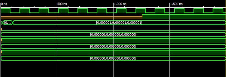
We are using Xilinx ISE for simulation of VHDL codes generated by MagCAD. Following is a screenshot of the output waveforms generated for 2D minority voter:2D minority logic output paramenters
We are treating 3 values marked by circles as t_prop, t_nuc and critical path respectively. The value marked by the arrow is being treated as latency. But these values differ from the values given in the paper by a very small difference for all designs. I have attached an excel sheet with a comparison between “the values given in the paper” and “the values generated by the tool”:
Excel sheet with a comparison between data.
Is the difference between the values acceptable? If not, then how to get the exact values?
Also, as you mentioned that the area is generated by the tool itself, I am unable to find the “bounding box area”. Kindly explain me the procedure to find the area.
-
This topic was modified 7 years, 6 months ago by lavish jain.
-
This topic was modified 7 years, 6 months ago by
 Fabrizio.
December 25, 2017 at 4:47 pm #1115Chinmay JoshiParticipantHi,
I am also using Xilinx ISE for simulation of the VHDL netlist. I am also not getting the same output as the one shown in the paper. Also, I wanted to know how to change the t_clock. Every time I export the VHDL code, a definition_pnml.vhd file is generated. When trying to simulate a design do we have to use the file specific to the design or is it fine if we use a general definition_pnml.vhd file. Like for example if I generate a VHDL file for full adder, can I use that definition_pnml.vhd file for a minority voter? or do I have to use the minority voter definition_pnml.vhd file?
December 26, 2017 at 4:23 pm #1120 FabrizioModerator
Hi Lavish,
I think that the values you got are a bit different because of the different grid size and the different nanowire width that you used within the design. Please look at the paper and check the parameters used in your design.
The automatic bounding box area calculation will be included in the next release that will be distributed in a few weeks. At the moment you can compute the bounding rectangle by looking at the maximum X and Y coordinate of your design.December 26, 2017 at 4:32 pm #1122FabrizioModeratorHi Chinmay,
some portions of the generated definition_pnml.vhd are strictly related to the design. As a consequence, you should use the generated “definition” files to simulate your circuit.
The minimum t_clock is automatically computed by the tool during the VHDL netlist extraction, according to the compact model associated to the technology. If you want to change it you can find it within the definition file. Keep in mind that reducing too much t_clock the circuit would not work properly.I hope I have clarified your doubts.
Fabrizio
December 27, 2017 at 4:13 am #1126Chinmay JoshiParticipantHi Fabrizio,
Thanks for clearing my doubt. I have another problem. When I try the minority voter circuit in MagCAD, the output comes that of a majority voter. This is true for the 2D voter. But in the case of 3D minority voter a random output sequence is generated. Same happens when I try to implement full adder. I guess it uses the majority voter principle.
December 29, 2017 at 2:32 pm #1127FabrizioModeratorHi Chinmay,
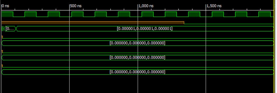
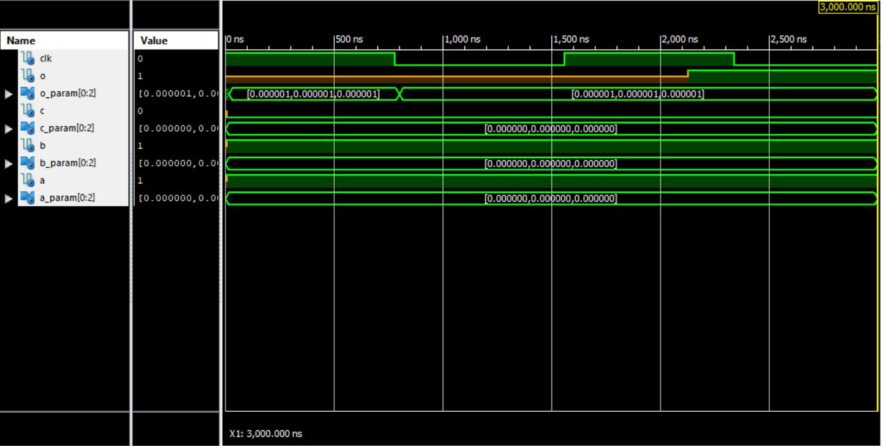
could you please upload the circuit’s layout and a meaningful portion of the waveforms of the 2D minority voter?
Thanks.
Fabrizio
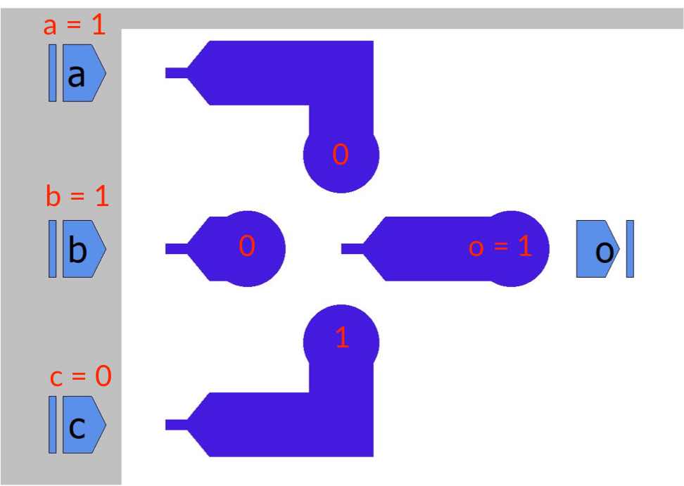
December 30, 2017 at 10:44 am #1129Chinmay JoshiParticipantThe output waveform is for the input a=1 b=1 c=0
Attachments:
December 30, 2017 at 2:37 pm #1135FabrizioModeratorDear Chinmay,
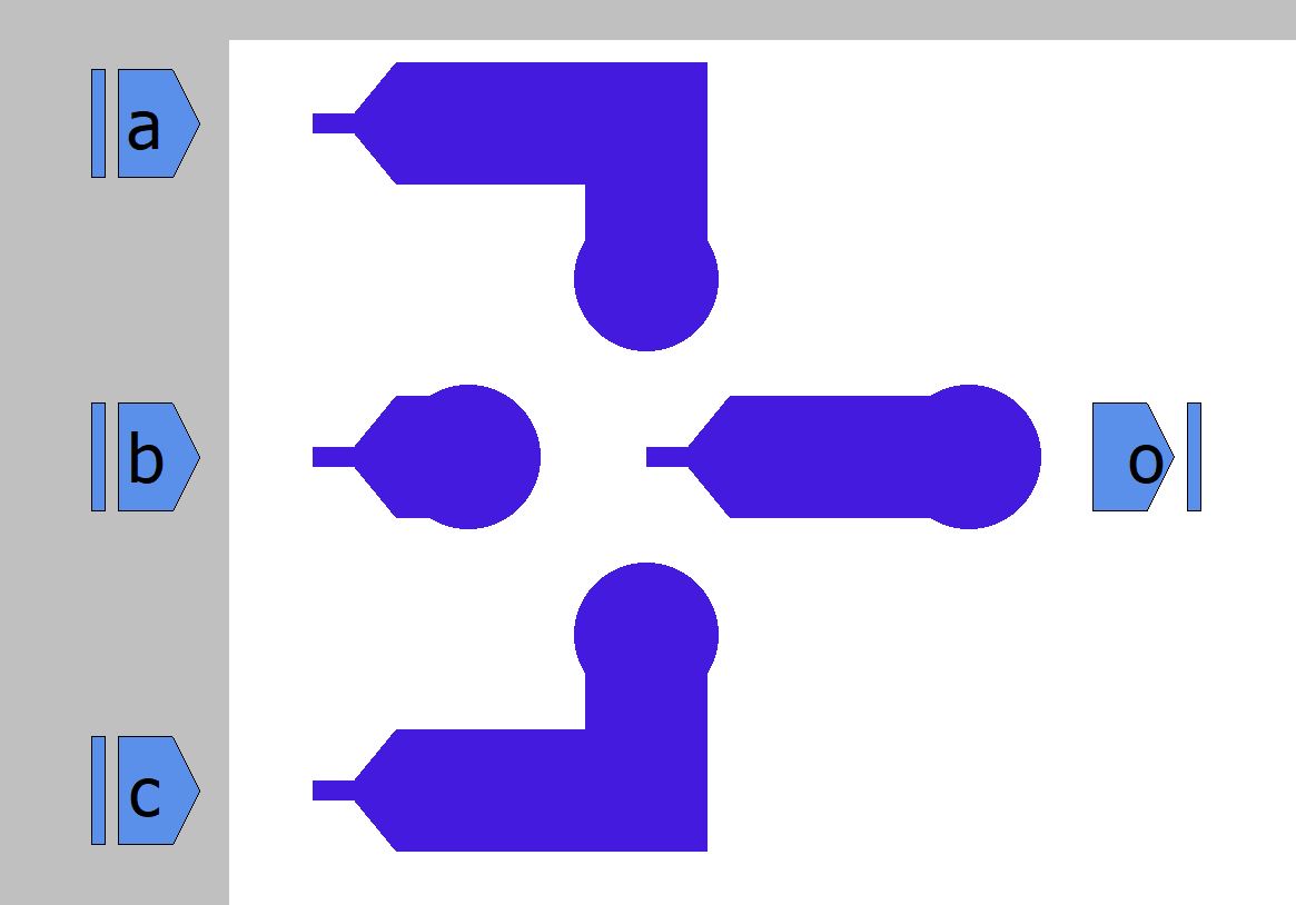
in the MagCAD user guide and in our paper, we consider as input of the minority the magnetisation of the 3 input magnets. Remember that if you apply a 110 within the testbech, you will get a 001 on the input magnets (because you have ANCs which work as inverters). As a consequence, the circuit output will be 1, which is the minority of the inputs. The attached image should clarify your issue.
Let me know if something is still not clear.
Fabrizio
Attachments:
December 30, 2017 at 2:52 pm #1137Chinmay JoshiParticipantHi Fabrizio,
Sorry I read that reversing of the inputs now. I got to know why my output wasn’t coming. Thanks for clearing my doubt.
-
This topic was modified 7 years, 6 months ago by
-
AuthorPosts
- The topic ‘pNML simulation parameters’ is closed to new replies.